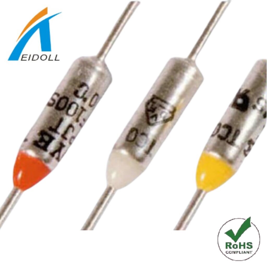
DYE Fuse DF Series Specification as below:
|
PAPT NO.
|
Tf(℃)
|
Th(℃)
|
Tm:VDE(UL)
|
EK
|
UL/CUL
|
VDE
|
CCC
|
PSE
|
|
DF50S
|
50
|
30
|
130
|
—
|
—
|
—
|
—
|
●
|
|
DF57S
|
57
|
37
|
130
|
—
|
—
|
—
|
—
|
●
|
|
DF66S
|
66
|
42
|
110(130)
|
●
|
●
|
●
|
●
|
●
|
|
DF72S
|
72
|
50
|
115(110)
|
●
|
●
|
●
|
●
|
●
|
|
DF77S
|
77
|
55
|
120(110)
|
●
|
●
|
●
|
●
|
●
|
|
DF84S
|
84
|
60
|
125(114)
|
●
|
●
|
●
|
●
|
●
|
|
DF91S
|
91
|
67
|
135(121)
|
●
|
●
|
●
|
●
|
●
|
|
DF98S
|
98
|
76
|
140(130)
|
●
|
●
|
●
|
●
|
●
|
|
DF100S
|
100
|
78
|
135(250)
|
●
|
●
|
●
|
●
|
●
|
|
DF104S
|
104
|
80
|
150
|
●
|
●
|
●
|
●
|
●
|
|
DF110S
|
110
|
88
|
140
|
●
|
●
|
●
|
●
|
●
|
|
DF115S
|
115
|
95
|
170
|
—
|
—
|
—
|
—
|
●
|
|
DF119S
|
119
|
95
|
170
|
●
|
●
|
●
|
●
|
●
|
|
DF121S
|
121
|
95
|
170
|
—
|
—
|
—
|
—
|
●
|
|
DF128S
|
128
|
106
|
155
|
●
|
●
|
●
|
●
|
●
|
|
DF132S
|
132
|
110
|
155
|
—
|
—
|
—
|
—
|
●
|
|
DF139S
|
139
|
117
|
170
|
●
|
●
|
—
|
—
|
●
|
|
DF141S
|
141
|
117
|
171
|
●
|
●
|
●
|
●
|
●
|
|
DF144S
|
144
|
120
|
250
|
●
|
●
|
●
|
●
|
●
|
|
DF152S
|
152
|
128
|
176(175)
|
●
|
●
|
●
|
●
|
●
|
|
DF167S
|
167
|
142
|
210
|
●
|
●
|
—
|
—
|
●
|
|
DF169S
|
169
|
145
|
300
|
●
|
—
|
—
|
—
|
●
|
|
DF170S
|
170
|
146
|
300(190)
|
●
|
●
|
●
|
●
|
●
|
|
DF179S
|
179
|
155
|
300
|
●
|
—
|
—
|
—
|
●
|
|
DF184S
|
184
|
160
|
300(214)
|
●
|
●
|
●
|
●
|
●
|
|
DF192S
|
192
|
162
|
290(222)
|
●
|
●
|
●
|
●
|
●
|
|
DF216S
|
216
|
—
|
241
|
●
|
—
|
●
|
●
|
●
|
|
DF222S
|
222
|
195
|
300
|
●
|
—
|
—
|
—
|
●
|
|
DF228S
|
228
|
193
|
300
|
●
|
●
|
●
|
●
|
●
|
|
DF240S
|
240
|
200
|
290(260)
|
●
|
●
|
●
|
●
|
●
|
|
DF260S
|
260
|
220
|
350
|
●
|
—
|
—
|
—
|
●
|
|
DF280S
|
280
|
230
|
350
|
●
|
—
|
—
|
—
|
●
|
file NO .EK:HH05009-2001A-2019A.5020A-5023A
UL/CUL:E117626
10. SOLDERABILITY
1) CONTACT LEAD
Soldering Bath Temperature ; 300℃
Immersing depth ; 2mm
VDE:40017388
PSE:JET2926-32001-1001-1011
CCC:2003010205079617
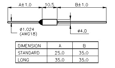
2. DIMENSIONS

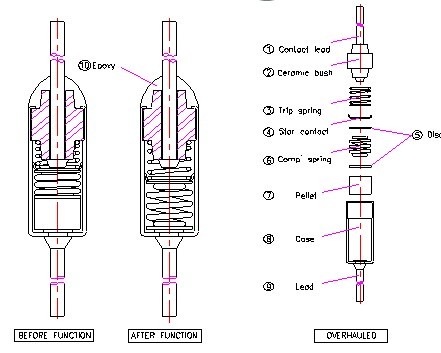
3. OPERATING PRINCIPLE & CONSTRUCTIONS
|
NO
|
DESCRIPTION
|
RAW MATERIAL
|
REMARKS
|
|
1
|
CONTACT LEAD
|
COPPER WIRE
|
SILVER-PLATED
|
|
2
|
CERAMIC BUSH
|
CERAMIC
|
|
|
3
|
TRIP SPRING
|
STAINLESS STEEL WIRE
|
|
|
4
|
STAR CONTACT
|
SILVER STRIP
|
|
|
5
|
DISC
|
PHOSPHOR BRONZE STRIP
|
|
|
6
|
COMPRESSION SPRING
|
STAINLESS STEEL WIRE
|
|
|
7
|
THERMAL PELLET
|
ORGANIC CHEMICAL
|
|
|
8
|
CASE
|
YELLOW BRASS STRIP
|
SILVER-PLATED
|
|
9
|
LEAD
|
COPPER WIRE
|
|
|
10
|
SEAL
|
EPOXY
|
|

4. CALIBRATION VERIFICATION
a. The samples of TCO are to be tested using electrically heated static-air oven.
b. Equilibrium conditions of oven temperature prior to the starting of the test are
to be established 10℃ below the rated Tf for 2 hours.
c. The temperature is then to be increased at a rate of 0.5℃/minute until the
TCO opened.
d. The opening temperature of each TCO shall not differ by more than plus 0℃
and minus 5℃ from the rated Tf.
5. THERMAL ELEMENT STABILITY(Aging)TEST
TCO are to be subjected to the following series of tests. Each sample shall
function at some time during the test steps.
Samples remaining intact at the conclusion of each step are to be submitted
to the next step.
STEP 1.
The samples are to be subjected to a temperature Tf minus 15℃ for 3weeks.
At the conclusion, at least 50% of the samples shall not have functioned.
STEP 2.
Tf minus 10℃ for 2 weeks
STEP 3.
Tf minus 5℃ for 1 week
STEP 4
Tf minus 3℃ for 1 week
STEP 5.
Tf plus 3℃ for 24hours
6. INSULATION RESISTANCE
Affer the fusing test of TCO, insulation resistance between lead and contact lead of
the test sample shall be more than 0.2MΩ. The insulation resistance to be
measured with a DC voltage of twice the rated voltage.
7. DIELECTRIC VOLTAGE WITHSTAND
TCO shall withstand for 1 minute without breakdown a 60Hz essentially
sinusoidal potential twice the rated voltage applied between leads or terminals
of an opened TCO.
8. DIELECTRIC RESISTANCE
Dielectric resistance measurement to be done between both leads at the
distance of 30mm including the body. Dielectric resistance shall be more than
1.5mΩ.
9. TEMPERATURE RISE
Temperature rising of TCO shall be not more than 10℃, when the r
rated
current to be passed through the TCO.


|


